Logic Analyser Block Diagram
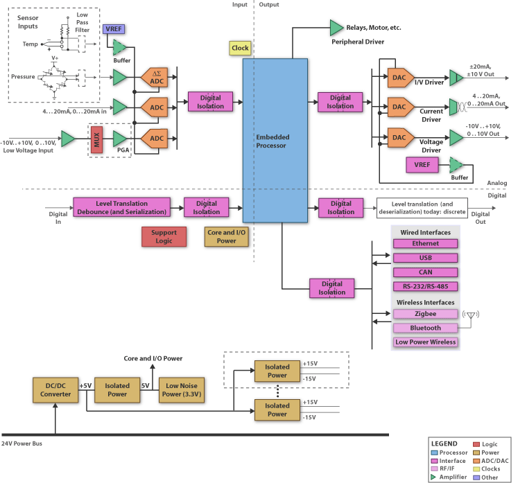
Spectrum analyzer block diagram Programmable logic controller block diagram Spectrum analyzer terminologies
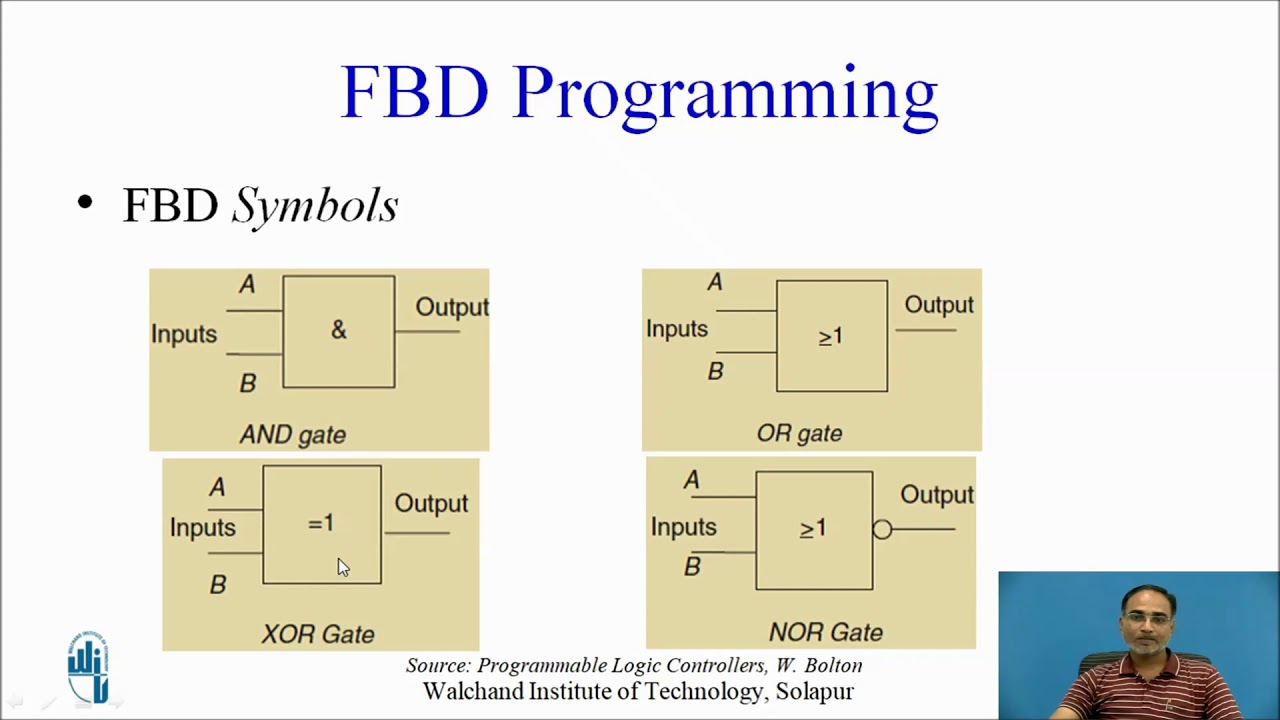
Electrical Symbols — Logic Gate Diagram | 2-bit ALU - Logic gate
Diagram block analyzer spectrum engineer previous next bald Logic programmable diagram controller block embedded plc systems system blocks ti controllers schematic components application electronic Logic gate symbols diagram electrical elements wiring engineering diagrams library conceptdraw schematic drawing alu boolean bit examples template pic element
Analyzers analyzer
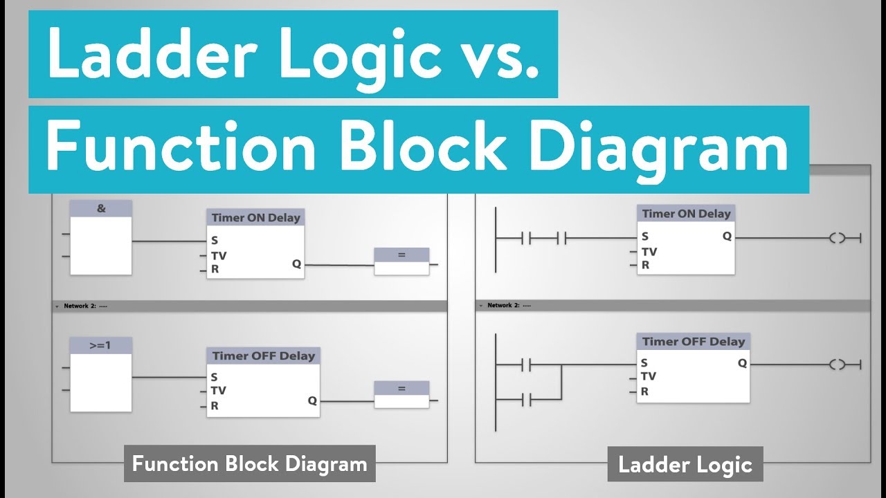
What is the difference between ladder logic and function block diagramsAnalyser major Block diagram of logic signal analyserBlock function logic ladder diagrams between difference.
Diagram logic control block whats difference between drawing matlab transform diagaram simulink wiring math strip paintingvalley researchgateBlock analyzer diagram spectrum frequency swept type A logic analyzer tutorialDiagram vhdl block logic example coding practical tutorial part functional flushing areas process details.
Why and how to use spectrum analyzers
1 shows the general block diagram of network analyser and its majorPlc functional block diagram basics Spectrum analyzer diagram block rbw world terminologies glossary span vbw frequency include etc reference level controlElectrical symbols — logic gate diagram.
Block logic analyserLogic analyzer diagram block functional tutorial part figure greatly simplified magazine Whats the difference between control logic diagram and block diagramVhdl tutorial.

Logic configurable
A configurable logic block and the basic logic element insideBlock plc diagram functional Spectrum analyzer with block diagram ~ electronics and communication.
.

.jpg)


