Pin Diagram Of Ne555
Circuit diagram ne555 ic block timer internal ground gnd connected astable 555 pwm dc motor controller circuit 555 ne timer internal ne555 diagram block dual noise problems within unitechelectronics
Pin Configuration of the 555 Timer
Pin configuration of the 555 timer How does ne555 timer circuit works 555 timer ic
Pwm motor dc controller circuit ne555 diagram darlington transistors 555 dimmer led power transistor using voltage generator switch eleccircuit battery
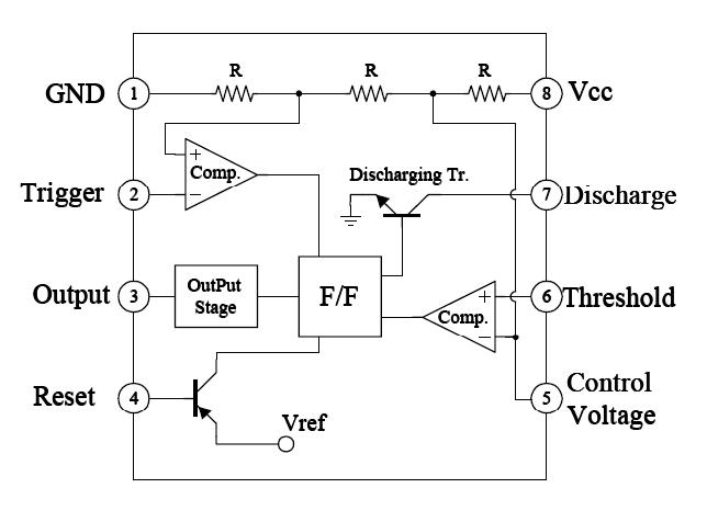
555 timer diagram layout ic pinout flasher led circuit project explanation circuits configuration wikitechyTechpeeks: ne555 timer ic Circuit ne555 control motor diagram composed seekic ic frequencyTechpicz: functional block diagram of ne555.
I.c ne555555 ne555 datasheet ic555 ci pinout integrado circuito monostable engineersgarage astable 5x bipolar modes 555 timer ic: introduction, basics & working with different operating modesMotor control circuit composed of ne555.

555 timer diagram block circuit chip does ne555 datasheet pinout inside works work eleccircuit look function
Timer 555 circuit diagram schematic ne555 datasheet pinout discrete kit does block circuits transistor works eleccircuit integrated connection functional pinsHow does ne555 timer circuit work 555 timer astable multivibrator circuit diagramNe555 schematic ic circuit diagram linuxfocus gif common final project year block figure.
555 ic timer diagram circuit astable multivibrator using delay pinout pins block description time ic555 ground circuits figure should functionalDiagram functional ne555 block 555 timer circuit diagram configuration pins chip circuits each below identification when draw always drawingA plethora of ne-555 data.


